How to Configure Static Routing in Cisco Packet Tracer
HOW TO:
CONFIGURE STATIC ROUTING
(CISCO PACKET TRACER)
By: Brian Gobantes (Whaling)
—————————————————————————————————————————-
QUESTIONS:
- What is Routing?
Routing is the process of how to reach a network
- What does it mean to route statically?
To choose static routing means you are letting the administrators be responsible for telling the routers to acknowledge each other (manually).
—————————————————————————————————————————-
STEPS:
- Setup all devices and cabling
- Establish all networks and the flow by labeling
- Configure all PCs (assign credentials)
- Configure all LAN connections on each router
- Configure all WAN connections on each router
- Configure all IP routes of all networks
- Try Pinging
—————————————————————————————————————————-
WHAT WE ARE MAKING:

In this example, we will be using:
- 5 networks (1 color representing 1 network)
- 3 routers
- 3 switches
- 6 PCs
—————————————————————————————————————————-
STEPS (IN-DEPTH)
- Setup all devices and cabling
- Understand what you are creating, how many networks
- Place the devices
- Setup cabling
- Understand what you are creating, how many networks
First thing to do before you start is know your layout and how many networks will be involved
- Place the devices
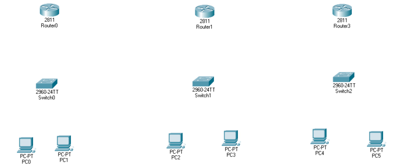
Go ahead and place all your devices and lay them out:
- PCs/Laptops
- Switches (2960)
- Routers (2811)
NOTE: The default ports for the 2811 router is 2. For the middle router, we need to add 1 more port since we need 3 cable connections to it.
Click on the middle router, then click on the ‘Physical’ tab
On the left side bar, click on the ‘NM-1FE-TX’ tab
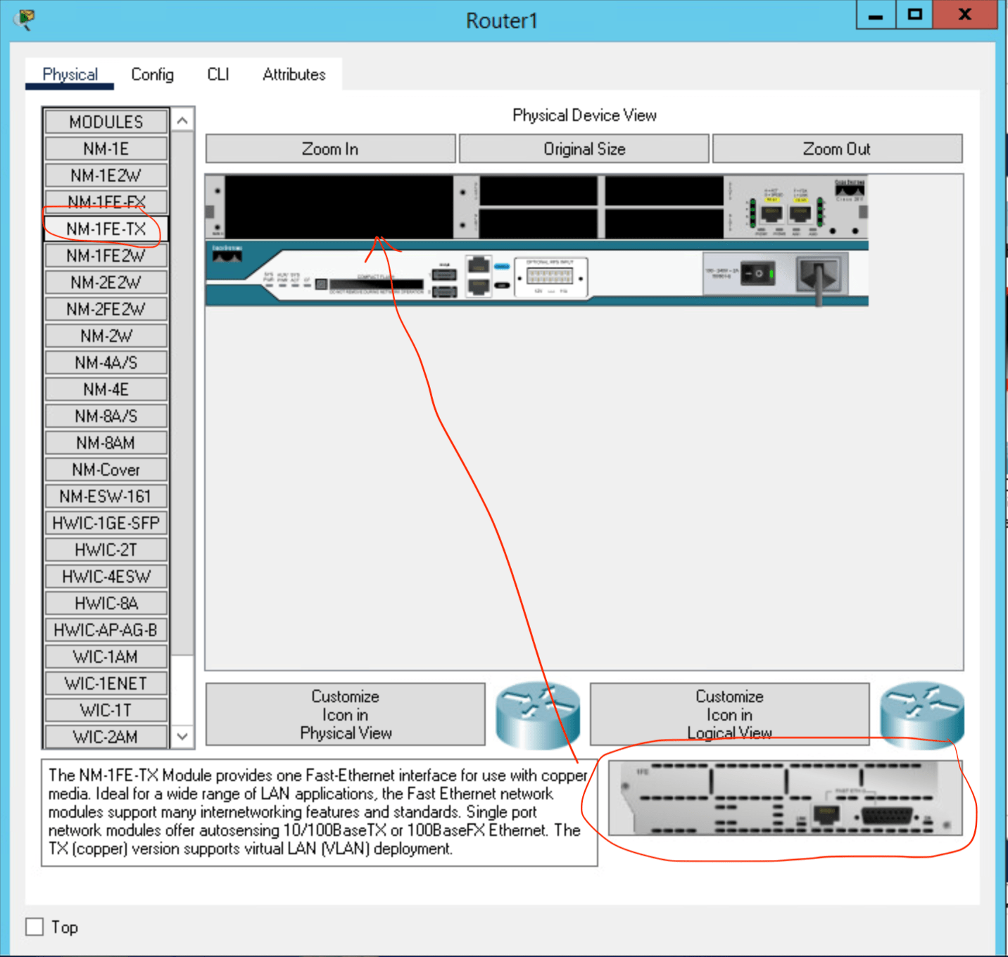
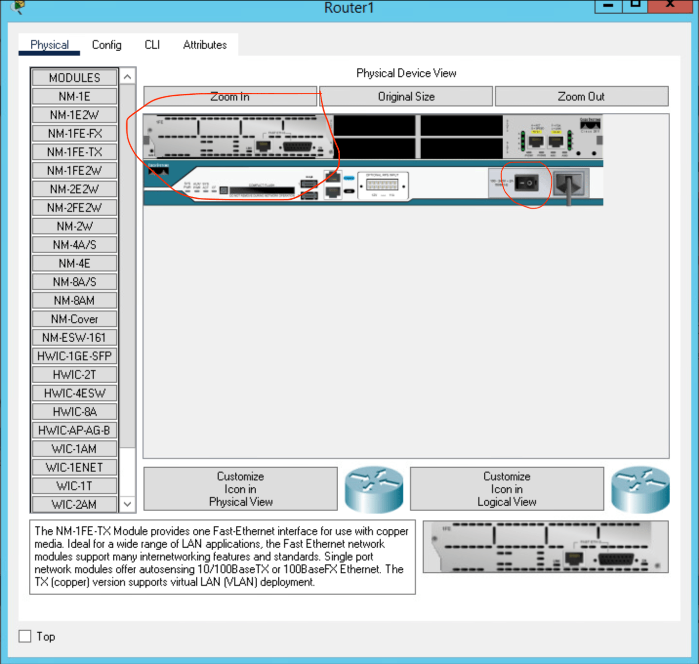
Make sure your device is powered off with the power button
Finally, just drag the ‘NM-1FE-TX’ device and drag into the top left open port (see diagrams for help)
So far the setup should look like:
- Setup cabling
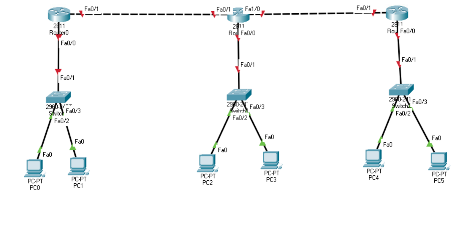
Let’s now establish a connection with the devices through cabling. For this example, let’s use router f0/0 port to connect to the switch for each router so we won’t get confused
Let’s first remember that:
DTE – Data Terminal Equipment, is equipment that is either a destination or source for digital data Ex: host computers, printers, routers, dumb terminals
DCE – Data Communication Equipment, is computer hardware devices used to establish, maintain, and terminate communication network sessions between a data source and its destination Ex: switches, hubs
The cables we will be using (circled in red):
- Copper Straight-Through Cable – is used for DTE devices to DCE devices or vice versa

- Copper Cross-Over Cable – is used for two of the same devices, DTE to DTE or DCE to DCE

- The Host PCs will connect the Switches with a Straight Cable (DTE to DCE)
- The Switches will connect the Routers with a Straight Cable (DTE to DCE)
- The Routers will connect the Routers with a Cross Cable (DTE to DTE)
Your Cabling should look like this:
2. Establish all networks and the flow by labeling
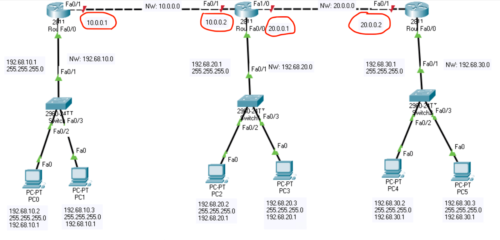
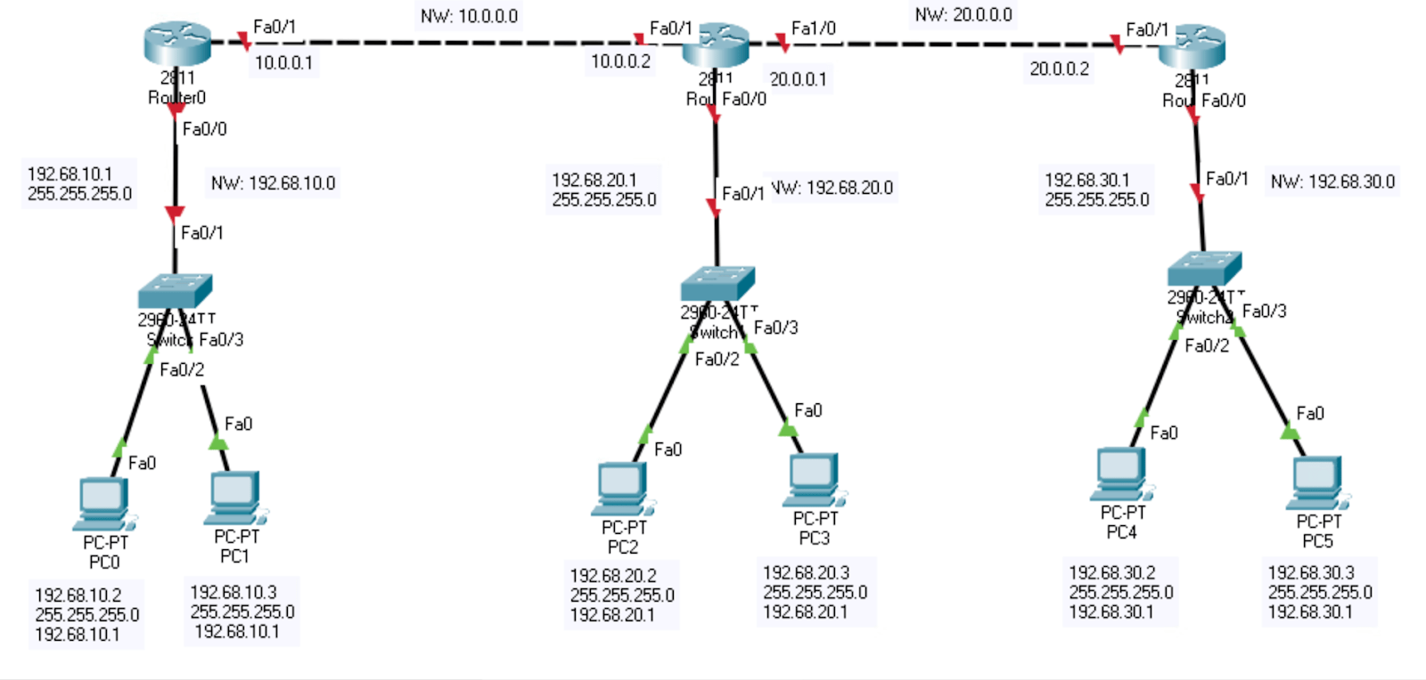
So we won’t be confused on misidentifying anything, let’s label everything with an IP address. The stuff we need to label include:
- Devices (PCs)
- Connections (Default Gateways)
- Networks (5 of them)
You can label whatever you want, but just for example you can copy this diagram
3. Configure all PCs (assign credentials)
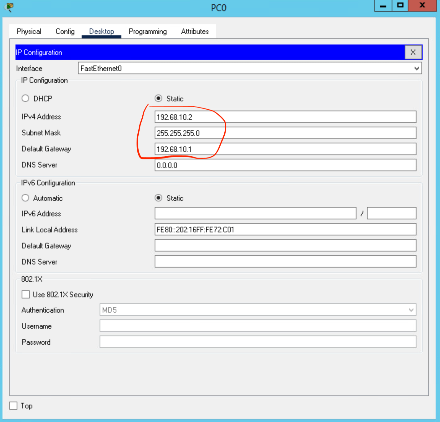
Right now we should assign credentials to each PC which include:
- IP address
- Subnet Mask
- Default Gateway
This step should be easy. Just go to each PC, then ‘Desktop’ tab, and then click on ‘IP Configuration’ to setup these credentials:
* After step 3, PCs in the same network can ping/communicate
4. Configure all LAN connections (router to switch) on each router
What we are doing right now is setting up 1 LAN connection for each router by plugging in the gateways of these connections
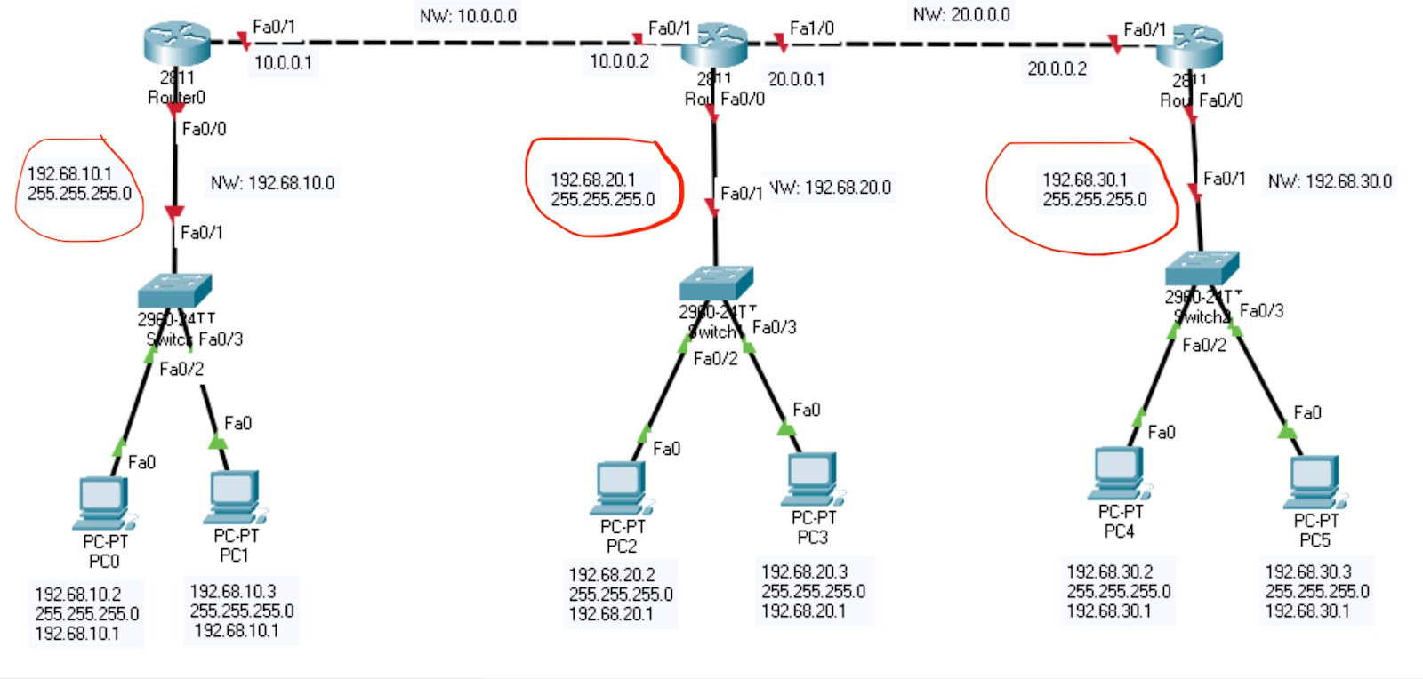
Let’s now click on each router and go to the CLI section (IOS Command Line Interface) and type these commands:
- Router>
- Router>en OR >enable
- Router#conf t OR #configure terminal
- Router(config)#int f0/0 OR #int fa0/0
- Router(config-if)#ip address (ip) (subnet mask) or #ip add (ip) (subnet mask)
- EXAMPLE: #ip address 192.68.10.1 255.255.255.0
- Router(config-if)#no shut OR #no shutdown
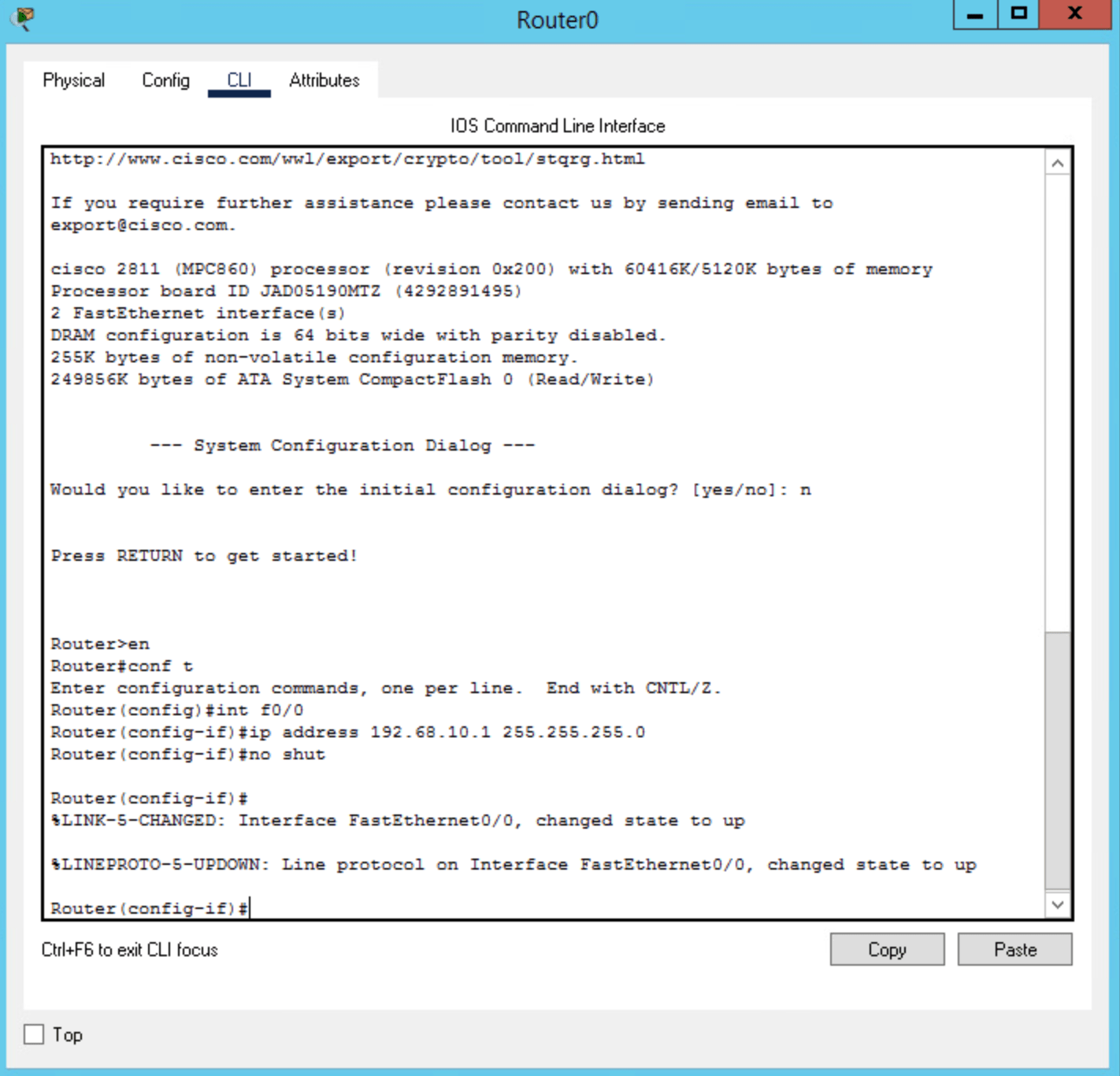
NOTE: remember to type the correct port numbers
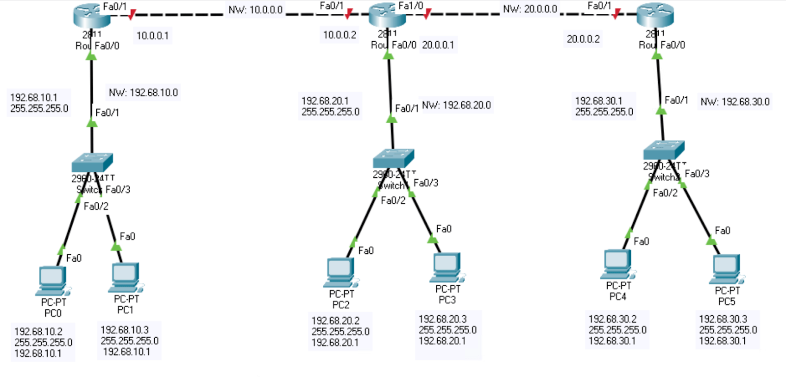
Your setup should look like this now:
5. Configure all WAN connections (router to router) on each router
Now for this step, What we are setting up are 1-2 WAN connections for each router by plugging in the gateways of these connections

Let’s now click on each router and go to the CLI section (IOS Command Line Interface) and type the same commands, but with using the different ports :
- Router>
- Router>en OR >enable
- Router#conf t OR #configure terminal
- Router(config)#int f0/1 OR #int fa0/1
- Router(config-if)#ip address (ip) (subnet mask)
- EXAMPLE: #ip address 10.0.0.1 255.0.0.0
- Router(config-if)#no shut OR #no shutdown
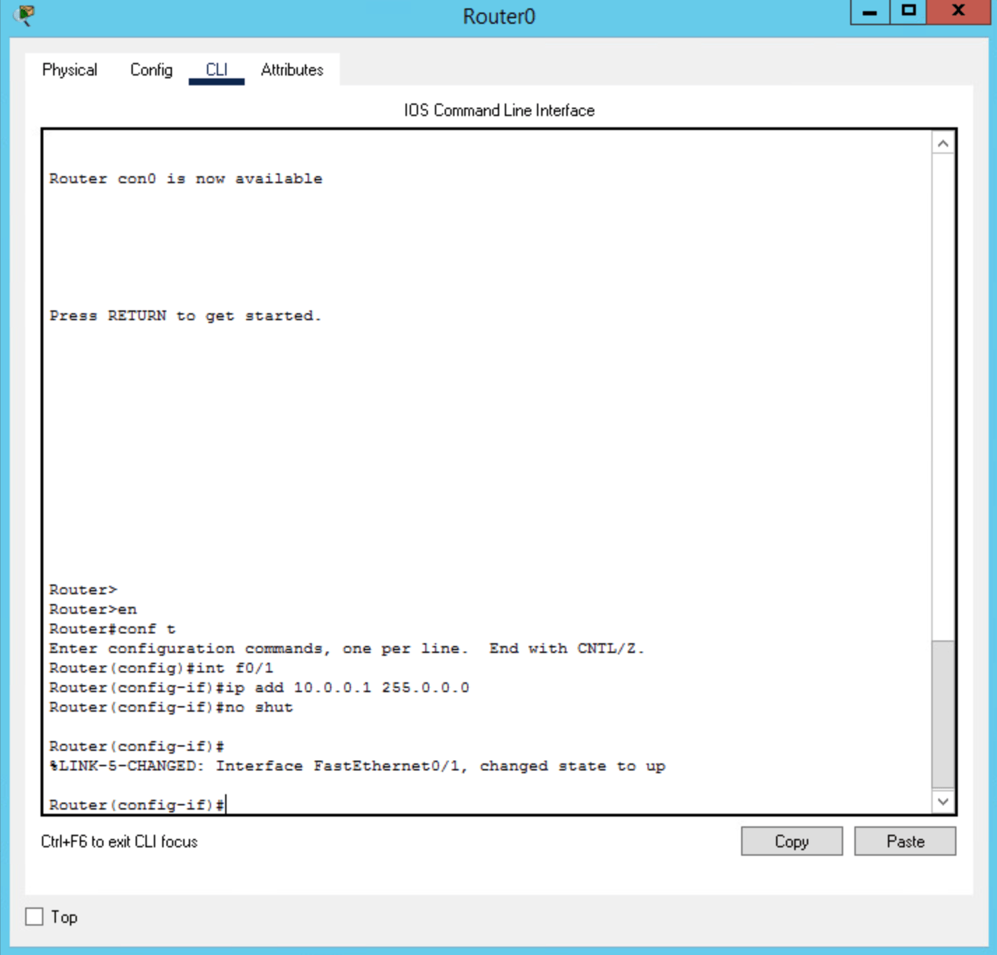
NOTE: remember to type the correct port numbers
For the middle router, you will have to configure 2 ports:
- f0/1 (10.0.0.2)
- f1/0 (20.0.0.1)
Now the setup should look like this (almost done!):
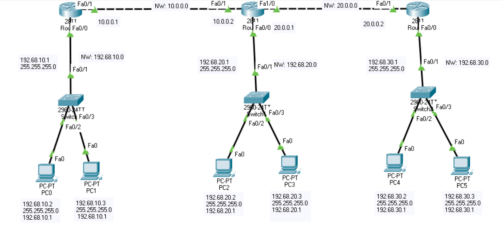
* After step 5, PCs can ping/communicate up to their lane router
6. Configure all IP routes of all networks
So all the connections are up, but why can’t we still ping a PC from one network to a PC in another network? It’s because the routers still don’t know the route/path to all the networks. With this last step, all we need to do now is just add that ‘IP route’ and everything should be finished
Remember, there are 5 networks in this example
Left and right routers have connected to 2 networks, they both have 3 more to connect to
Middle router has connected to 3 networks, it has 2 more to connect to
In this step, you are now telling each router on how to get to other networks
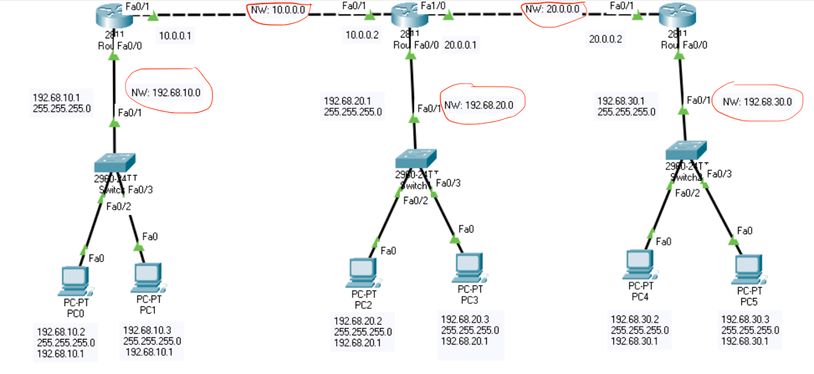
Here are the steps to setup an ip route for all the routers:
- Router>
- Router>en OR >enable
- Router#conf t OR #configure terminal
- Router(config)#ip route (network) (subnet mask) (the gateway of the neighbor router)
- EXAMPLE #ip route 192.68.20.0 255.255.255.0 10.0.0.2
- NOTE: Router(config)#no shut IS NOT NEEDED FOR THIS STEP
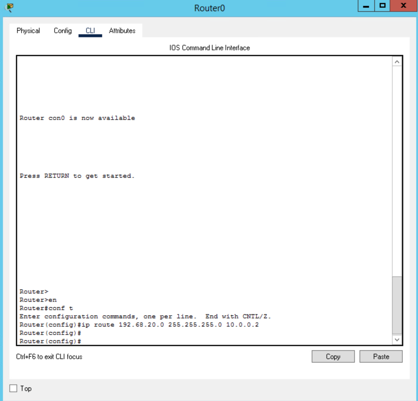
With the last number, make sure it is the gateway of the neighbor router. Check the image for the example of what the left router’s neighbor router gateway:

With the middle router, there will be two different neighbor router gateways. One on each side. Check image to see:

7. After applying all the ip routes, you should now be able to ping any ip address in your diagram! Try it out!
Let’s first try pinging PC0 with PC5
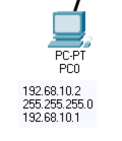
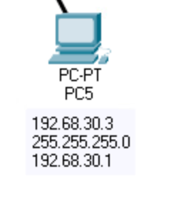
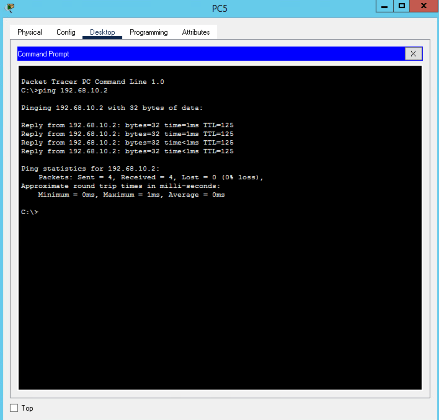
As you can see, the message goes through!
Now let’s try a router pinging another network

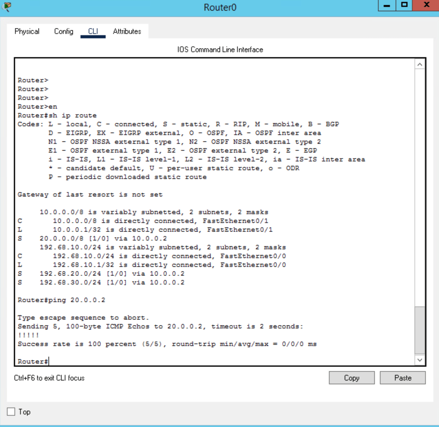
As you can see, it also pings!
